1:pump body components
Usually gear pump by gear and impeller, pump shaft, motor, pipe, valve and pump shell this part, impeller installed in the pump shell and fastening on the pump shaft, pump shaft directly driven by the motor.
There is a liquid suction pipe in the pump shell. The liquid enters the pump through the bottom valve and suction pipe. The liquid discharge outlet on the pump shell is connected with the discharge pipe.
2:Pump body structure principle
(1) Before the pump starts, the pump shell is filled with the transferred liquid. After the pump starts, the impeller is driven by the shaft to rotate at a high speed, and the liquid between the blades must rotate as well.
(2) Under the action of centrifugal force, liquid is thrown from the center of the impeller to the outer edge and energy is obtained, leaving the outer edge of the impeller at a high speed and entering the cochlear pump shell.
In the volute, the liquid slows down due to the gradual expansion of the flow passage, and converts part of the kinetic energy into static pressure energy, and finally flows into and out of the pipe at a higher pressure.
(3) When the liquid flows from the center of the impeller to the outer edge, a certain vacuum is formed in the center of the impeller. As the pressure above the liquid storage tank is greater than the pressure at the pump inlet, the liquid is continuously pressed into the impeller.
As long as the impeller keeps rotating, the liquid will continue to be inhaled and discharged
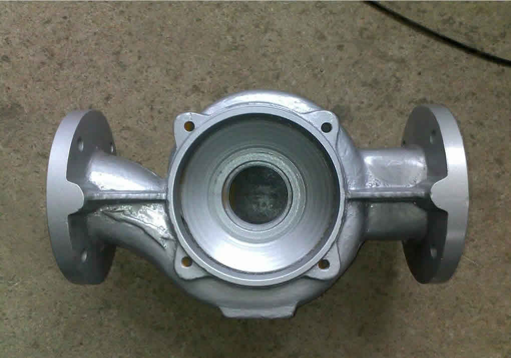
3: Pump shell manufacturing process
The key point of the pump shell manufacturing process is to ensure the correct position of the assembly datum hole surface and the flow passage of the pressurized water chamber.
Pump shell is mostly finished in vertical lathe and boring machine. It can cut multiple sides in one clamping.
The process line of pump shell using boring machine is:
(1) use the bottom foot pad to precisely locate the right runner and then clamp it. Separate the inlet and outlet flanges to ensure that the flanges are parallel and coincide with the center of the runner.
(2) with the inlet flange on the operating table to find the right channel after pressing, car quasi impeller assembly end of each hole face.
(3) then lock the bottom foot of the vehicle after the operation table rotates, ensuring the position accuracy of the assembly hole surface and flow passage.
4: impeller manufacturing process
Impeller is a CNC turning parts, the common process line is:
(1) clamp the outer diameter or back mouth ring of the impeller with four claws, use the flow channel center or front and rear cover plate flow path surface as the axial alignment reference and the impeller inlet diameter as the radial alignment after clamping, rough impeller inlet ring to leave fine running margin and front plate surface.
(2) clamp the third jaw impeller orifice ring after aligning the workpiece, turn the back orifice ring, outer diameter, inner hole and back cover plate well, to ensure the concentricity requirements of inner hole, outer diameter and orifice ring.
(3) after positioning the manometer shaft with the inner hole of the impeller, finish turning the front orifice ring of the impeller to ensure the concentricity requirement of the front orifice ring and the inner hole.
(4) three jaw spider coupling after the mouth ring or outside diameter to find the right inner hole keyway, to ensure the symmetry of the keyway;
(5) drill the balance hole of the impeller to ensure that the blade spacing is not damaged;
Motor bracket manufacturing process
The motor bracket structure is usually connected with the motor at one end and the pump body at the other end. If the center is different, quality problems will occur.
Common turning processes are:
(1) hold one end of the four claw alignment, the other end of the rough fine car.
(2) install and calibrate the tire size on the lathe, install the matching hole at one end of the third car into the tire to find the positive pressure, coarse and fine car pump body connection end size, so that the two ends of the concentricity can be guaranteed.
(3) finally, the bolt connection holes are drilled through the drill tool.
Manufacturing process of pump shaft
The pump shaft is mainly based on the central hole as the positioning datum. In order to ensure the radial runout requirement, the clamping method of the top of both ends is usually adopted. The high-precision matching surface is usually completed by grinding machine.
Process route:
(1) for roughing, drill the center holes at both ends, clip one head to make roughing and transfer the allowance to the heat treatment process;
(2) semi-finishing, the heat treatment of the shaft must repair the central hole, clip a top end of the semi-finishing, and complete the thread on the shaft, cutting groove, etc..
(3) seiko, for the parts with low requirements, use the top of both ends of the heart clip, will cooperate with the part of the outer circle fine car;
(4) finally, milling machine and grinder are used to complete the keyway and cylindrical process. Attention is paid to ensure the symmetry of the keyway milling.